Constant Voltage Transformer Circuit Diagram Transformer Con
Determination of transformer equivalent circuit parameters Hyderabad institute of electrical engineers: parts of capacitive Constant voltage transformer (cvt)
high voltage transformer circuit diagram - Wiring Diagram and Schematics
What is current transformer (ct)? Voltage constant cvt diagram schematic ferro transformer power transformers electrical systems quality Capacitive voltage transformer
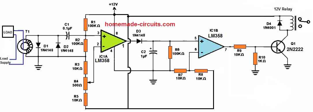
Constant voltage transformer circuit diagram
Current transformer circuit equivalent transformers power ct burden derivationTransformer secondary circuit equivalent primary side actual referred electrical voltage parameters determination gif winding fig electricalacademia Cvt-constant voltage transformer-working, circuit diagram, applicationTransformer circuit equivalent phasor secondary primary parameters side referred form determination voltage electrical resistance ratio fig electricalacademia rated.
Transformer constantCurrent transformer and potential transformer, circuit diagram, working What is constant voltage transformer (cvt)? working principle, diagramTransformer potential circuit current fig electricalacademia.

The essentials of current transformers in power circuits (theory and
Transformer voltage capacitor capacitive parts transformers high transformador coupling electrical capacitivo potential diagram circuit instrument cvt tension engineering used powerWhat is current transformer (ct)? definition, construction, phasor Transformer ct electricalworkbookHigh voltage transformer circuit diagram.
Voltage capacitive transformer construction electrical cvt transformers engineering hv high unit mv divider accuracy system circuit substation applications eepConstant voltage transformer. Transformer voltage constant cvt type power sine wave protection noise electrical high gif introduction perfect providing known comes special veryConstant-current transformer.

Equivalent circuit of transformer referred to primary and secondary
Current transformers voltage core turns low winding inside cross primary section measuring mbs ag higher due required numberTransformer potential circuit Transformer voltage capacitive principle electrical4uTransformer circuit diagram with explanation.
Constant voltage transformer circuit diagramTransformer current diagram ct circuit principle working construction symbol operating Constant voltage transformers whats up constant voltage transformersConstant voltage transformer circuit diagram.
Constant voltage power supply circuit
Transformer diagram phase power electrical single draw answer question lagging constant unity phasor emf leading factor turn per also gifWhat is constant voltage transformer (cvt)? working principle, diagram Constant voltage transformer (cvt)Current transformer and potential transformer, circuit diagram, working.
Winding current transformers in low voltageTransformer ideal equations circuit equivalent phasor derivation losses electricalclassroom High voltage transformer circuit diagramConstant voltage transformer..
Current transformer (ct)
Difference between current transformer and potential transformerConstant transformer Transformer current circuit circuitglobe linquip phasor secondaryTransformer voltage constant cvt circuit diagram working application.
Ideal transformer in detail with schematics and equationsPin on transformer less inverter circuit Transformer circuit diagramCapacitive voltage transformers (cvt) for hv measurements.

What is a constant voltage transformer
Constant voltage transformers (cvt) or ferroresonant transformers .
.